

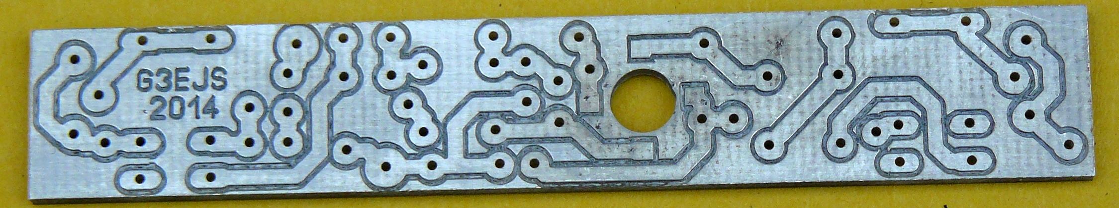

The new board. Most of the copper that is not tracks will be connected to ground via intentional solder bridges
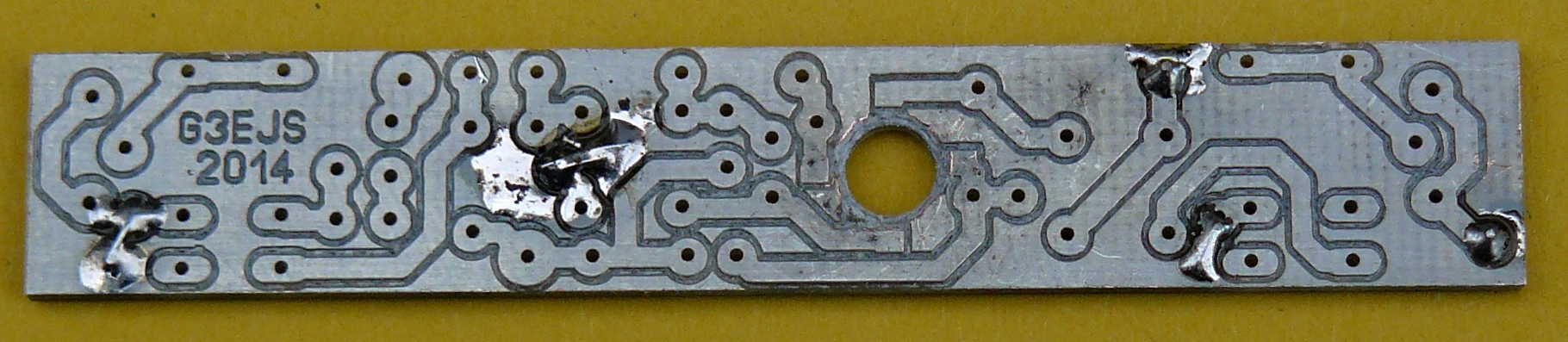
First the links from the ground plane (component side) to the ground tracks are made. Keep the solder and wire on the ground plane side as small as possible, to prevent it getting in
the way of the coils or relays. The FET mounting hole has been “countersunk” to remove copper that would short the leads to ground.
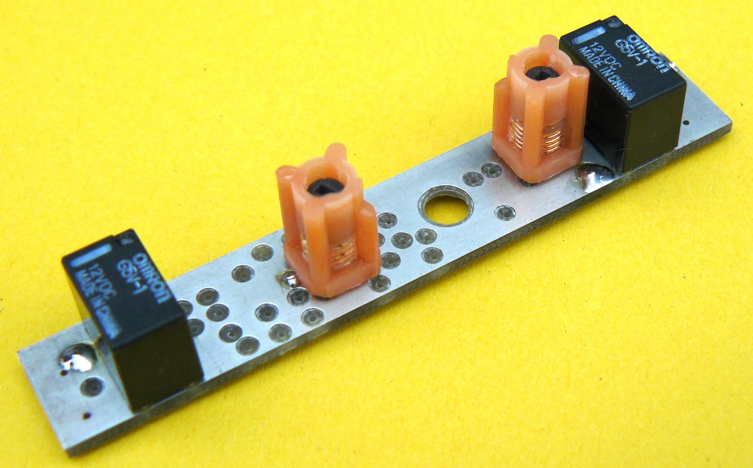
I find it easier to fit the coils and relays first. Some components are a tight fit, and might make it hard to get the coils or relays straight.
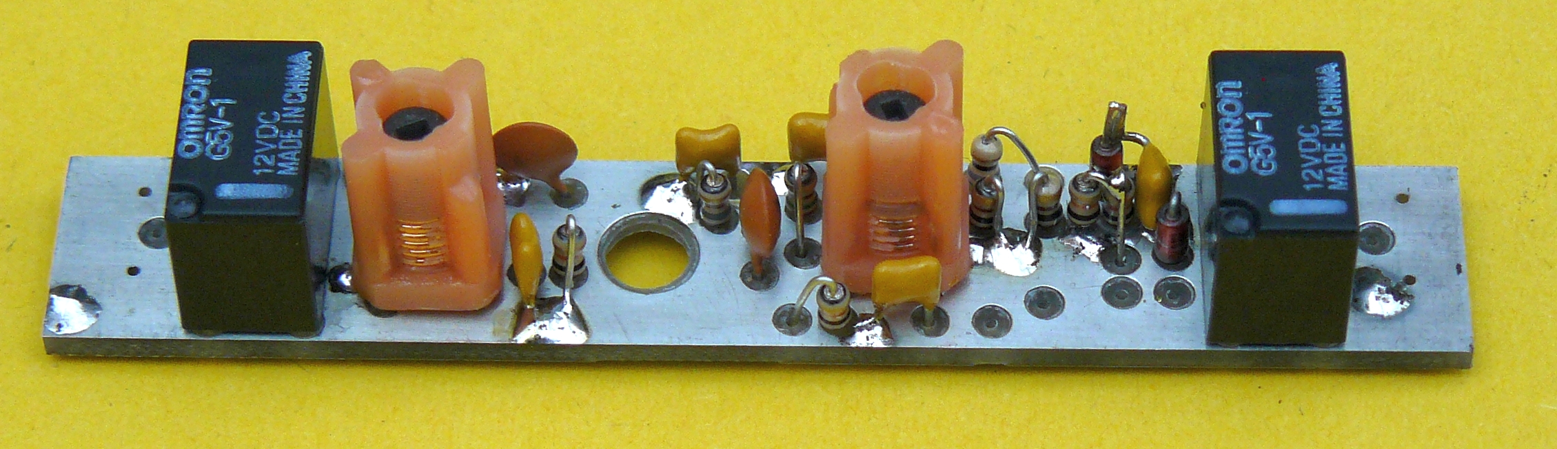

General view with most of the components fitted. Notice the orientation of the coils, one “corner post” is shorter than the others.
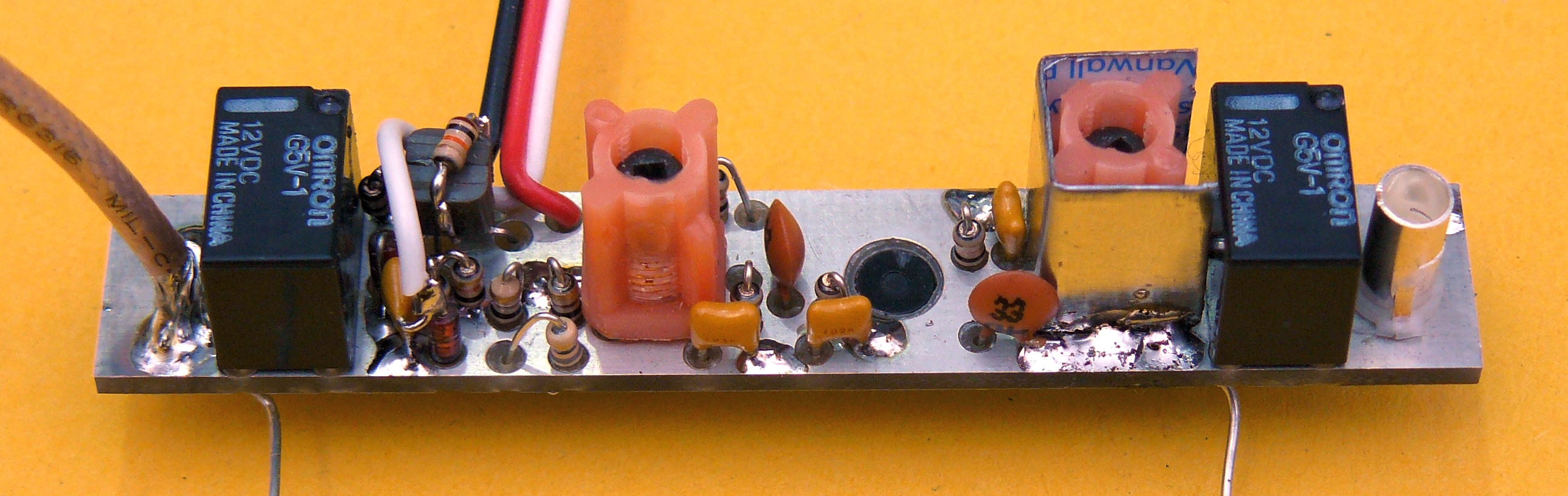
The completed board. Note the filed mark on the FET, inline with the long leg. They are all the same length when cut to fit, and very easy to fit the wrong way round.
I no longer use a screen across the board on the FET, instead there is a screen on the input coil. More in the NOTES
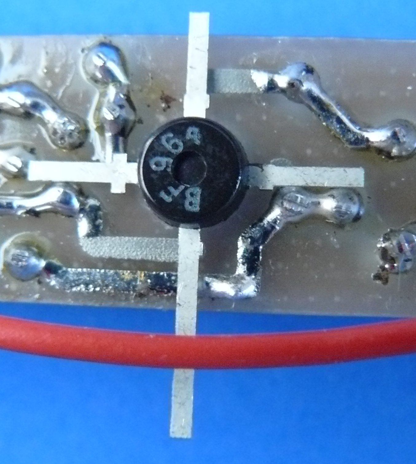
I ran out of BF981s, the BF964 has about 0.25dB more noise on 4m. Note which way up it is and which leg goes where. File a mark into the FET before cutting off the legs in case you get interrupted!
Some of the BF964s I had were not marked, and only had a white painted side, this painted side faces the same way as the writing above.
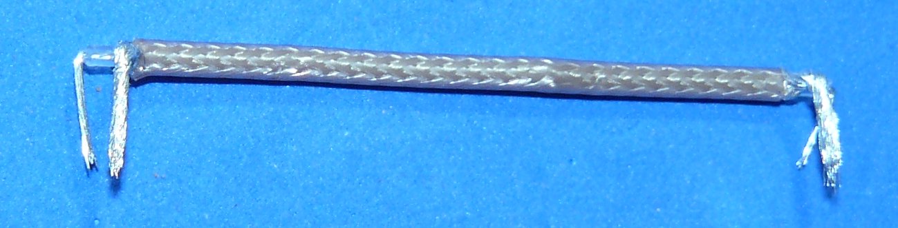
Shape the bypass link before tinning the wire, once it has solder on it, it is not easy to shape

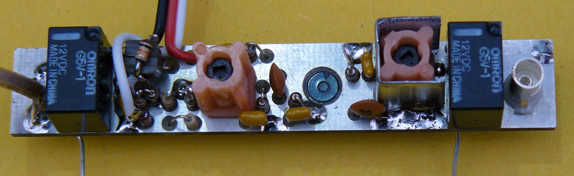
The bypass link joins the NC contacts of the two relays. The orange wire joins the coils of the two relays. (this is the original prototype PCB, but it more clearly shows the connection points)
Photos of the finished amp

Ensure when shaping the supporting wires that there is space between the inductor cans and the bottom of the board, and that the speaker wire will have room to fit.
Put a straight edge across the aluminium on each side and ensure there is a gap between it and the preamp board.
Make sure there are no wires on top of the aluminium before refitting the metal plate with the speaker