
The board was designed for a transistor I thought I had, but did not! I have now used two common transistors, any thing similar should work.
I will try and describe how I put it together, hopefully the pictures will show as well.
I have no intention of changing the board, I don’t think the components would fit anyway.
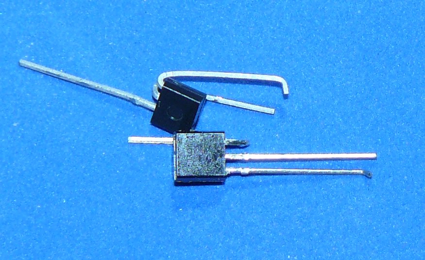 The first thing to do is to file a mark on the curved side of one of the transistors so that it can be identified,
Then bend the collector lead of the 2N3904 and the base lead of the 2N3906 up around the curved side of the transistors.
Then with a dab of superglue, glue the two flat sides of the transistors together, and join the collector and base leads previously bent up with a 10k resistor (R24)

Then bend the emitter lead of the 2N3904. This will connect to R23

Fit D22 and D21. Next to D21, fit C21, the top junction of C21 and D21 will connect to the control signal from the 847 to activate the relays.
Then fit R21 and R22. The bottom of R22 solders onto the ground plane, and the top onto the top of R21.
From the other side it looks like this
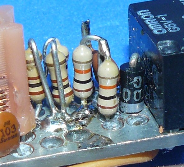
Then the transistors are fitted

Care should be taken that the transistors don’t protrude past the edge of the board (it won’t fit in the space in the 847!) This means some careful bending of the leads to make them fit and ensure they don’t short.
R23 is fitted between the ground plane and the bent up emitter of TR21